
How To Read Hydraulic Circuit Diagram
Business Industry Hydraulics Preview this course Learn to read and understand hydraulic circuit symbols Explaining fluid power symbols and how to interpret the hydraulic circuits that use them 3.7 (12 ratings) 73 students Created by Gary Molton Last updated 2/2021 English English [Auto] What you'll learn

How to read Hydraulic Schematic Diagram YouTube
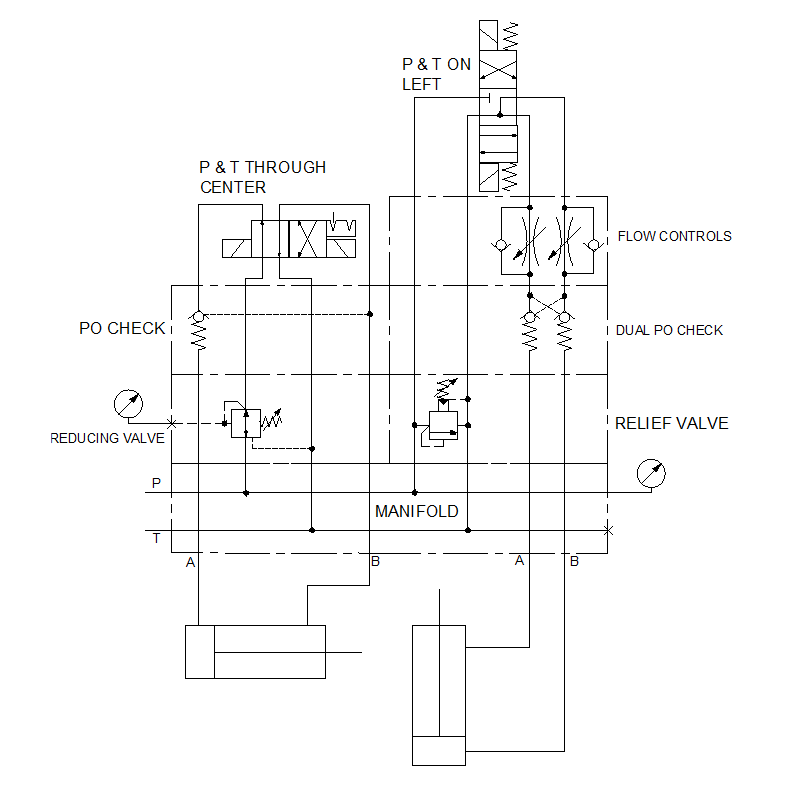
Case 1: Hydraulic cylinder activation This basic hydraulic circuit of activating one hydraulic cylinder uses a three layer stacked valve assembly. First, it takes system pressure (normally ~2000 psi) and passes it through a pressure reducing valve (set for 560 PSI). In the figure this is the lower dashed rectangle of the three layer valve assembly.
How To Read Hydraulic Schematic Drawings Wiring Diagram
The basics of how to read hydraulic schematics and recognize basic component types.

how to read a hydraulic schematic Wiring Work
In this lesson we'll review schematic symbols for common fluid power devices including fluid conductors, prime movers, pumps, reservoirs, actuators, directio.

How to trace hydraulic circuit (Part 4) Double acting cylinder with variable load takes place
The first step to reading a hydraulic circuit is to familiarize yourself with its components. The most common components include valves, pumps, hoses, tubing, tanks, manifolds, and hydraulic cylinders. Knowing what these components are and their purpose will make it easier to understand the circuit's working principles.
How To Read A Hydraulic Schematic Diagram Wiring Diagram
Reading fluids circuit diagrams - hydraulic & pneumatic symbols Dec 19, 2017 Below are some common illustrations of equipment located on fluids circuit diagrams, followed by descriptions of the most common elements. Later in this article series we will describe some simple hydraulic and pneumatic circuits composed of these circuit elements.
How To Read Hydraulic Circuit Diagram Pdf Circuit Diagram
How to read hydraulic circuits Hydraulics symbols are an essential component of hydraulic circuit diagrams. Knowing some of the basic principles will help understand a wider range of symbols. Explaining the common ISO1219 symbols enables a complete hydraulic system to be followed: 1. Hydraulic Pump Hydraulic pump produces flow.
Hydraulic Circuit Diagram Animation
Pipelines Pipelines on hydraulic circuits are shown with lines connecting the elements. The control lines are represented by a dotted line. The direction of fluid flow is indicated by arrows, if necessary. Some lines are designated by letters: P - pressure line, T - line drain, X - control line l - drainage.

How To Read A Hydraulic Schematic Circuit Diagram
Basic Electrical Knowledge https://www.youtube.com/playlist?list=PL8zOygNOyBo1Nq53tdaSt1FfoIjMIV52FNEC PLAYLIST PRACTICE TESThttps://www.youtube.com/playlist.
How To Read Hydraulic Circuit Diagram
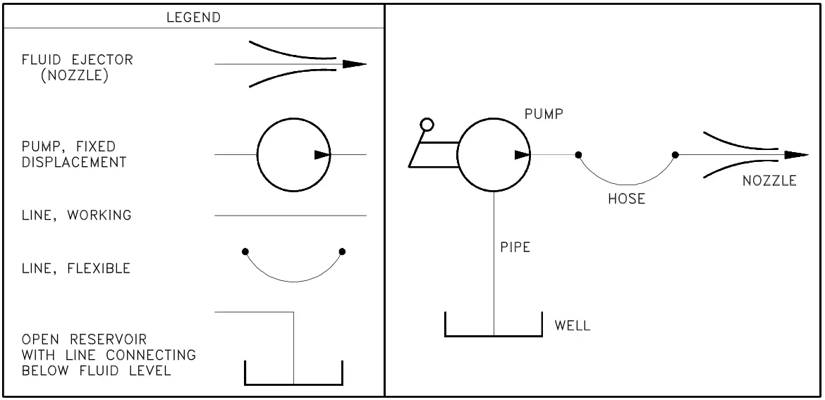
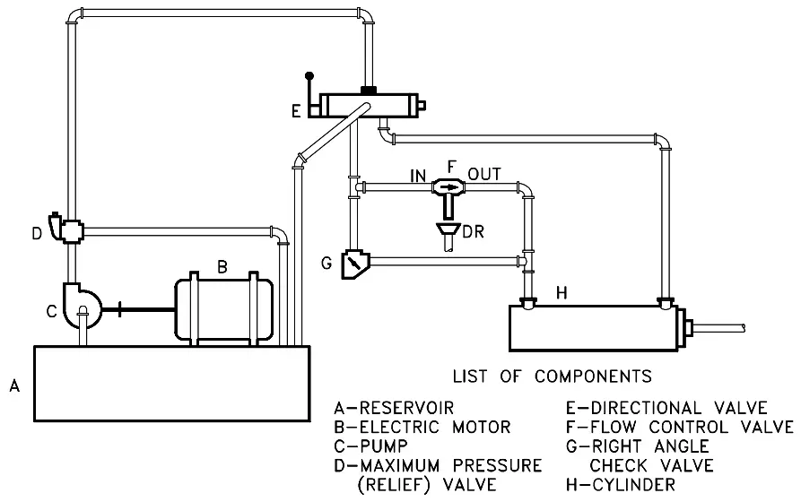
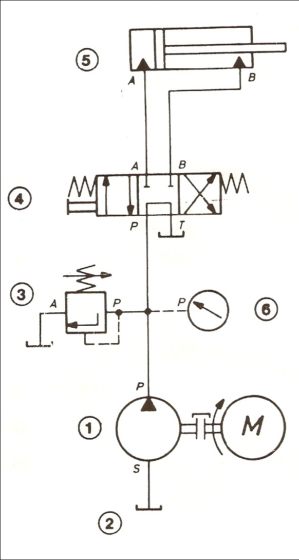
Reading Fluid Power Diagrams. Using the symbology previously discussed, a fluid power diagram can now be read. But before reading some complex examples, let's look at a simple hydraulic system and convert it into a fluid power diagram. Using the drawing in Figure 27, the left portion of Figure 28 lists each part and its fluid power symbol.
How To Read Hydraulic Schematic
A hydraulic circuit diagram is a complex visual representation of a hydraulic system. It shows the relationships between components and how they interact to produce a desired result. Understanding such diagrams is essential for any hydraulic engineer, maintenance engineer, technician or operator.

A guide to common hydraulic symbols EngineeringClicks
Below is our hydraulic symbiology glossary outlining elements of specific Carr Lane ROEMHELD parts, including check valves, power units, relief valves, control valves, pressure gauges, hydraulic circuits, variable displacement pumps and more. Carr Lane provides engineers with valuable resources.
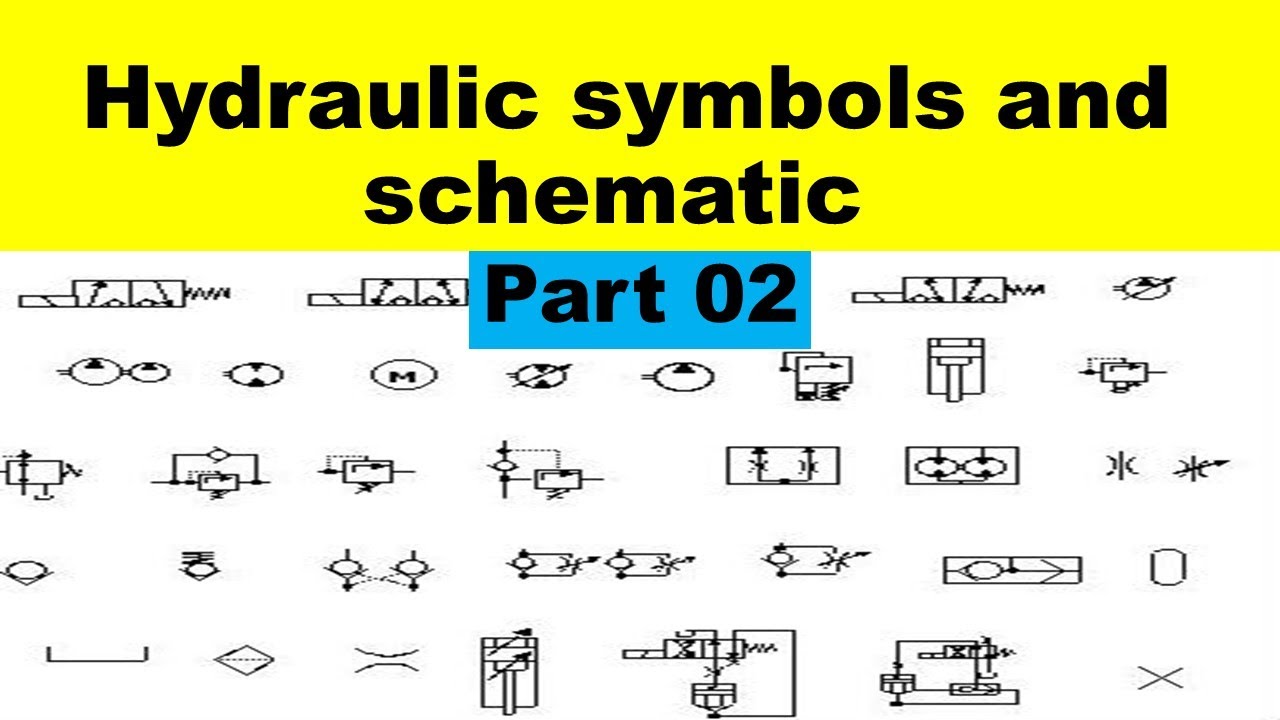
Hydraulic Symbols and Schematic For Beginners How to Read Hydraulic Drawing. Part 02
Understanding how to read hydraulic circuits is the key to designing, constructing, and troubleshooting your machines efficiently. The first step to reading hydraulic circuits is familiarizing yourself with the various symbols used to represent the components of the circuit.

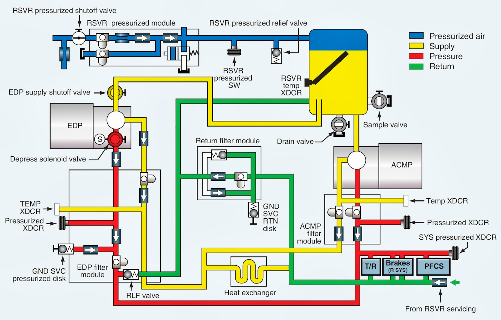
The hydraulic circuit diagram of a plant with two actuators. Download Scientific Diagram
Schematic reading is one of the most important skills when working with complex hydraulic systems. We are going to spend a handful of videos looking at diffe.
How To Read A Hydraulic Schematic Diagram Wiring Diagram
First things first - identify the symbols. Hydraulic schematics use a wide range of symbols to represent different parts and connections. Familiarize yourself with these symbols by consulting books or manuals that describe what each symbol stands for. This will make it much easier to interpret the schematic. Next, pay attention to the arrows.

How To Read A Hydraulic Schematic Diagram Wiring Diagram
The first step in learning how to read a hydraulic circuit is to understand the various components involved. This includes pumps, valves, reservoirs, flow meters, flow controllers, and more. It's important to understand how each component affects the overall system and how it works together to create the desired effect.
